
An IGBT (Insulated Gate Bipolar Transistor) is typically described as “a combination of a field effect transistor and a bipolar transistor in which an N-channel FET controls a bipolar transistor.” Although this sentence accurately describes the fundamentals, the complexity of the IGBT control circuit in high power IGBT applications is much higher than in the control of a small MOSFET. Because the currents required in a MOSFET for switching are typically negligible, control of a MOSFET is commonly referred to as no load.
This is unquestionable in the case of high-power IGBTs, where several watts of control power are frequently required. Furthermore, internal capacitances that must be reloaded and play little role in the control of small MOSFETs cannot be ignored in this case.
IGBT control is a complex process that requires a driver that is tuned to the IGBT. Furthermore, most modern isolated gate drives include protection circuits and safety functions to safeguard the IGBT in the event of a malfunction, which would otherwise result in the IGBTs total destruction.
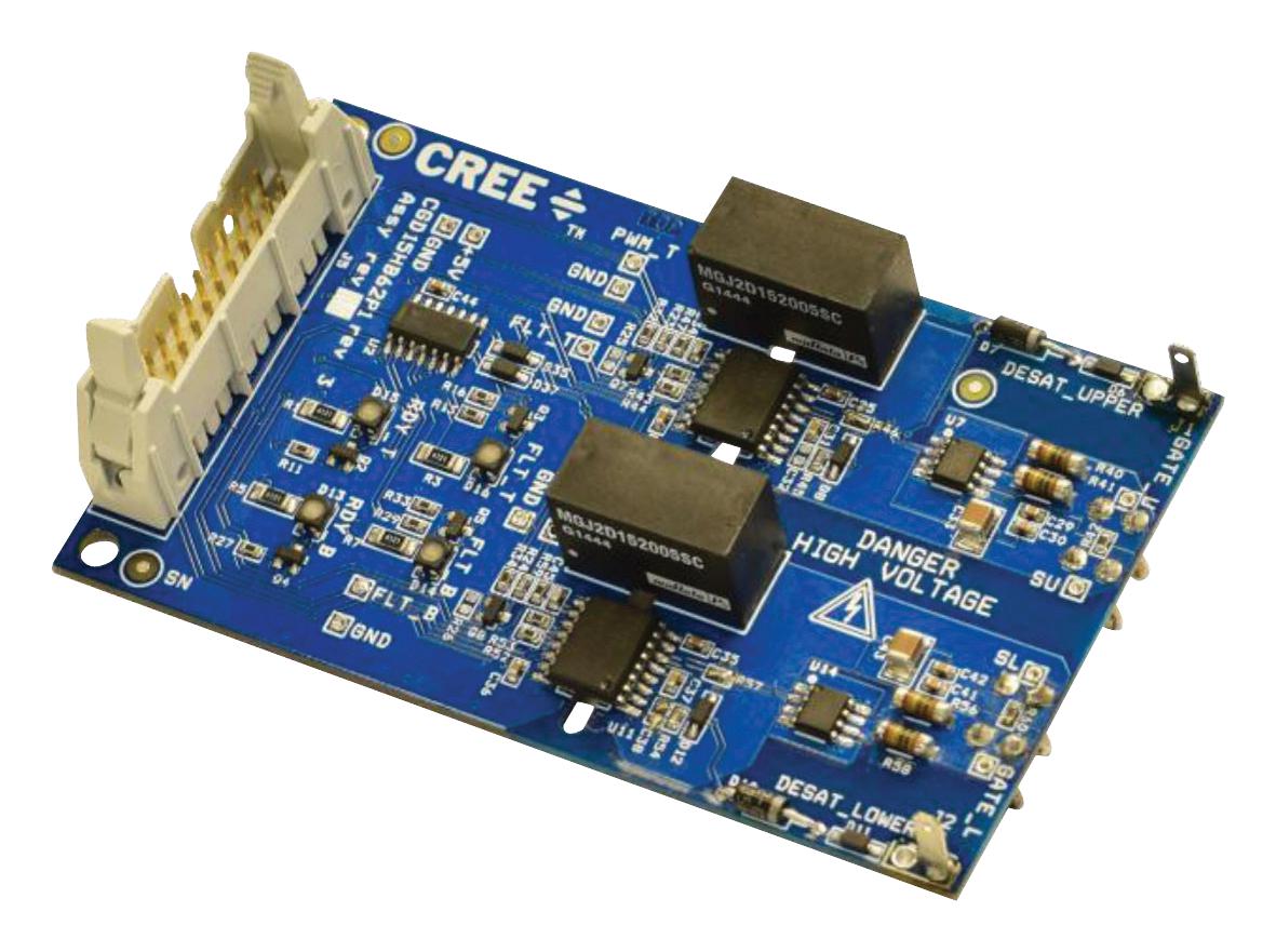
In the presence of higher reverse voltages, voltage isolation of the input (low-voltage) and output (high-voltage) circuits is mandatory. The output circuit is directly connected to the high-voltage IGBT, whereas the input circuit serves as an interface to the control electronics (Figure 1). Figure 2 depicts an optically controlled 2-channel IGBT driver board.
Electrically Isolated Control of IGBTs
Electrical isolation between the control signal and the isolated gate drive circuit is required in nearly all IGBT applications. The electrically isolated control signals and feedback signal (error signal) can be transmitted in three ways:
- Capacitive Coupling
- Inductive Coupling
- Optical Coupling
While the capacitive solution is rarely used, the inductive and optical coupling solutions are. When dealing with low to medium voltages, optical couplers are commonly used, whereas transformers and optical fiber are used when dealing with high reverse voltages (> 1200 V). Since there is no way to transmit enough power for control electronics and IGBT control via optical signal transmission, a transformer solution is almost always used for power transmission.
As a result, transformers are used to transfer control and feedback signals, particularly in the medium to high voltage range. In theory, this solution is also applicable at higher voltages; however, as the voltage increases, so do the transformer’s space requirements, ensuring that the minimum clearance and creepage distances are maintained.
Optical transmission can thus demonstrate its advantages at higher reverse voltages (> 1200 V). As shown in Figure 3, the IEC 664-1:1992 standard specifies a minimum distance of several centimeters at higher voltages. For a fiber-coupling, such distances are extremely short. Inductive or capacitive coupling, on the other hand, can already be expensive and take up a lot of space on the board.
Table 1 summarizes again the benefits and drawbacks of each solution.
Table1. Methods of Galvanic Isolation
Fiber Optic
An optical fiber connection is typically used in high-voltage systems to transmit control signals, as well as status and error signals. The theoretically infinite isolation that can be achieved over a realizable distance is a clear advantage when compared to all other galvanic isolation technologies.
Transmission over several kilometers is technically possible using multi-mode fiber (MM) or single-mode fiber (SM) and wavelengths of 850nm or 1310nm. However, much more frequently, it is necessary to transmit only a few feet or even inches, and in this case, the transfer of a polymer optical fiber (POF) with a wavelength of 650nm has been shown to be optimal. The use of POF provides not only a cost-effective solution, but also makes cable handling and preparation easier than with MM and SM fiber.
Another advantage of using fiber transmission is that the optical transmission path is completely immune to electromagnetic radiation. As a result, if the fiber is laid near strong electro-magnetic radiation components, as is common in industrial environments, there is no problem at all.
A short link can be used as an alternative if the required isolation voltages are only a few thousand volts. These devices provide the benefits of an optical fiber connection while being able to be installed directly on the board and without the need for any assembly. The clearances in this case are determined mechanically.